1.
ADC
·
The
world around us is analogue in nature and the microcontroller usually
understands only digitial information .ie. Whether input is there or not.
·
There is
a built in Analogue to digital converter inside the microcontroller which could
be used to read the input voltage given to the ADC pins of the µC.
·
AVcc and
AGND are the pins to power on the ADC peripheral and we use the voltage given
in AREF as the analogue reference voltage.
·
There is
a 10 bit counter inside the µC for counting the ADC input as the fraction
of AREF voltage. So the ADC has got a resolution of 10-bit and it has got an operational
speed of 15kSPS (Kilo Samples per Second)
·
We need
to set two registers for using ADC:
i.
ADCSRA –
ADC Control and Status Register
ADEN: This bit
is set to enable the ADC.
ADSC: This bit
is set to start an ADC Conversion
ADIF: ADC
Interrupt flag set by the hardware when a conversion is over.
ADIF: ADC
Interrupt mask bit.
ADSPx : ADC
prescaler bit. ADC Sampling works well at a frequence range of 50kHz to 200kHz.
So we need to prescale the system clock value down to a value within that
frequency.
ii.
ADMUX –
ADC Multiplexer
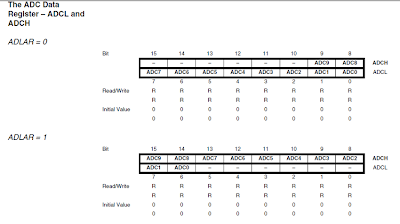
This register is being mainly used to set the ADC source, ADC reference
source and also the ADC bit alignment selector
·
ADC
could be used in 8-bit and 10-bit modes.
·
We will
be having ADCH and ADCL as the ADC counter. If we are using the 8-bit mode then
we could get the maximum reading as 255 and in 10bit mode we could get it as
1023.
·
In 8 bit
mode the input voltage will be (ADC_count * VREF) / 255
·
In 10
bit mode the input voltage will be (ADC_count * VREF) / 1023
#include
<avr/io.h>
#include
<util/delay.h>
#include<avr/interrupt.h>
void
main()
{
DDRB = 0b00000111; //Green in PB0, Yellow
in PB1, Red in PB2
PORTB = 0x00;
ADCSRA = (1<<ADEN) | (1<<ADSC)
| (1<<ADIE);
ADCSRA|=(1<<ADPS2)|(1<<ADPS1)|(0 << ADPS0); //Setting
the prescaler
ADMUX = (1<<ADLAR)|(1<<MUX0)|(1<<MUX1)|(1<<MUX2);
//ADC7 for I/P
sei();
while(1)
{
}
}
ISR(ADC_vect)
{
uint8_t x = ADCH; //Using the 8-bit ADC
mode
if( (((float)x*5)/255) > 3.5)
{
PORTB = 0x02;
}
else if( (((float)x*5)/255) < 1.5)
{
PORTB = 0x01;
}
else
PORTB = 0x04;
ADCSRA |= (1<<ADSC);
}


No comments:
Post a Comment